 |
As the FT-847 does not have a Band Data 1 (4-bit band data code) interface, the Quadra will work with it on the same basis as with a non-Yaesu exciter, as described here.
|
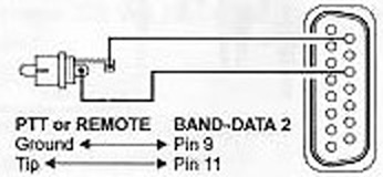
The Band Data 2 cable is made up as illustrated in Fig.1:
VL-1000 Band Data 2 (DBM15) Pin 9 to Ground (shell of PTT RCA plug).
VL-1000 Band Data 2 (DBM15) Pin 11 to PTT (centre pin of PTT RCA plug).
 |
Insert the RCA plug on the Band Data 2 cable into the FT-847 PTT jack (RCA).
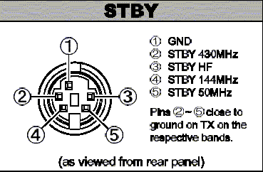
Connect STBY (amplifier keying) cable as follows:
VL-1000 PTT1 (RCA) plug shell to FT-847 STBY Pin 1 (Ground). Refer to Fig.2.
VL-1000 PTT1 (RCA) plug centre pin to FT-847 STBY Pin 3 (HF).
VL-1000 PTT2 (RCA) plug shell to FT-847 STBY Pin 1 (Ground).
VL-1000 PTT2 (RCA) plug centre pin to FT-847 STBY Pin 5 (50 MHz).
Insert RCA plug into VL-1000 PTT1 jack (RCA), and 5-pin mini-DIN plug into FT-847 STBY jack.
Connect VL-1000 ALC1 (RCA) to FT-847 ALC (RCA).
Note: For 50 MHz operation, connect VL-1000 ALC2 (RCA) to FT-847 ALC (RCA).
Connect VL-1000 INPUT 1 to FT-847 HF coax socket via coax jumper.
Connect VL-1000 INPUT 2 to FT-847 50 MHz coax socket via coax jumper.
Connect VP-1000, VL-1000 and FT-847 ground lugs to station ground point with braid or suitable wire.
Select FM or RTTY for band selection (F SET) and auto-tuning (TUNE). The VL-1000 requires at least 50W drive for proper tuning and band selection.
The VL-1000 keys the FT-847 via the exciter's PTT jack to obtain a tuning carrier; the VL-1000 counts the excitation frequency and sets itself to the correct frequency range. Once the ALC is set as per the VL-1000 user manual, the VL-1000 will deliver 1kW output (HF) with approx. 75W drive. (De-rate to 500W on 50 MHz.) Please refer to main Quadra page. See also FT-847 user manual, pages 5 and 29.
View Joe Subich W4TV's FL-7000/FT-920 interface.
Copyright © 2005-2022 A. Farson VA7OJ/AB4OJ. All rights reserved. Last updated 10/09/22