|
|
Connecting the Yaesu VL-1000 (Quadra) to the FT-1000MP/MkV |
|---|
by Adam Farson, VA7OJ/AB4OJ |
based on an FT-1000MP Reflector discussion with Bill Heinzinger, W9OL, 15/16 November 2002 |
 |
Reprogram the VL-1000 amplifier per Yaesu's instructions, to activate 10 and 12m; this reconfigures the amplifier as the "International" model.
On the exciter, set Menu item 7-9 to the default value "EL" (FT-1000MP) or "Keyer" (FT-1000MP MkV & Field). Also, set Menu item 4-3 (Exciter Drive Power) to MAX (FT-1000MP), 75 (FT-1000MP MkV) or HI (FT-1000MP MkV Field). The VL-1000 requires at least 75W of drive for correct auto-tuning or bandswitching.
Set the REMOTE switch on the VL-1000 rear panel to ON (up). This will allow the exciter's POWER switch to power the VL-1000 up and down. (VL-1000 user manual, page 8).
Connect the VL-1000 to the MP or MkV via 4 cables: RF, ALC (mandatory), BAND DATA 1 (8-pin DIN) and BAND DATA 2. Connect the ALC cable from the ALC 1 jack on the VL-1000 to the ALC jack on the MP. Note: The BAND DATA 1 cable provides a PTT line (Pin 2) to the VL-1000, thus eliminating the need for a separate PTT cable. It also provides a transmit inhibit (TX INH) line (Pin 8: +12V inhibited, 0V enabled) to the MP, MkV or Field, for QSK Tx/Rx switching control.
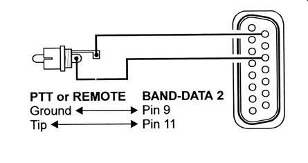
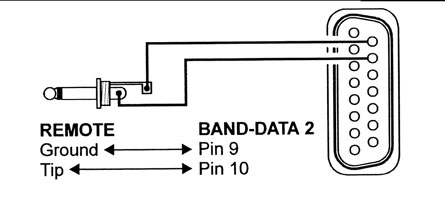
The instructions for connecting the BAND DATA 2 cable are on page 4 of the VL-1000 user manual. The supplied cable is fitted with an RCA plug is to accommodate non-MP exciters. (See Figure 1). For use with an FT-1000MP, MkV or Field, cut off the RCA plug, connect a 3mm mono mini-phone plug and rewire as shown in Figure 2. (Refer to VL-1000 user manual, pages 3 and 4). The FH-1 Remote Keypad can be connected in parallel with the BAND DATA 2 cable via a 3mm "Y" adapter.
Connect the BAND DATA 2 cable between the VL-1000 BAND DATA connector (DB15) and the MP/MkV REMOTE jack. This cable allows the VL-1000 to key the exciter for tuning when the F.SET or TUNE button is pressed.
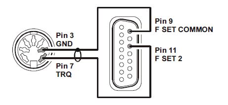
For the FTDX-9000, cut off the RCA plug on one end of the Band Data 2 cable supplied with the Quadra, and connect a 7-pin 260° DIN plug as shown in Figure 3. Insert the plug into the exciter's BAND DATA 2 socket.
ALC calibration: Set the VL-1000's ALC level to limit power output to 1 kW, corresponding to approximately 80W of drive. It is sufficient to calibrate the ALC on one band; the power output is almost constant across all HF bands. (VL-1000 User Manual, p. 12.)
Automatic Bandswitching & Tuning: With a Yaesu FT-1000MP, MkV or MkV Field, or FTDX-9000 as exciter, the tuning cycle consists of two processes:
The BAND DATA 1 (4-bit DIN) cable is connected between the exciter and amplifier BAND DATA 1 sockets.. The 4-bit code sent to the VL-1000 on the BAND DATA 1 cable (Pins 4, 5, 6 and 7) sets the bandswitching relays to the band selected on the transceiver, and also selects the antenna port initially programmed for that band. (VL-1000 user manual, page 10).
The BAND DATA 2 cable (DB15 to 3mm mono) is connected between the VL-1000 BAND DATA 2 jack and the MP's REMOTE jack to allow the next step to take place. Note: The Quadra emulates the TUNE key on the FH-1 Remote Keypad by applying a 25.5kΩ loop between Pins 9 and 10 of the BAND DATA 2 cable.
When the F.SET or TUNE button on the VL-1000 front panel is pressed, the amplifier keys the exciter, which in turn transmits a CW carrier to the amplifier. The VL-1000's CPU counts the excitation frequency, and initiates band selection F.SET or tuning TUNE. When the band-selection or tuning cycle is complete, the VL-1000 unkeys the exciter. The TUNER screen of the VL-1000 displays COMPLETE if tuning is successful. (VL-1000 user manual, page 13).
When the autotuner has been tuned on a given frequency, the VL-1000 will memorise the tuner settings. When the exciter is tuned to that frequency range again, pressing F.SET will set the tuner to the closest memorised tuning point. This takes less time than a full tuning cycle. (VL-1000 user manual, page 7).
If the BAND DATA 2 cable is not connected, pressing F.SET will have no effect. Pressing TUNE will start the autotuner, but in the absence of a carrier the tuner will stop almost immediately with an ERROR display.
Autotuner Matching Range: The reflectometer at the autotuner output will report a HI.SWR error for load SWR > 3:1. There appears to be a slight non-linearity in the power/SWR relationship of this reflectometer, so at full power the amplifier may report a HI.SWR error for load SWR > 2.75:1.
Cooling: The fans in the VL-1000 RF cabinet can cycle on and off, or run continuously at low speed, depending on ambient temperature. They will speed up when the amplifier is keyed. The fans in the VP-1000 power-supply cabinet cycle on and off. (VL-1000 user manual, page 10). It is recommended to leave at least 10 cm (4 in) of clear space around the top, sides and rear panel of both cabinets, to ensure adequate air-flow. The feet should also be locked in the elevated position.
Barefoot Operation: If the VL-1000 RF unit is turned off via its POWER button, and the VP-1000 power supply is powered up, the ANT1 relay (RL7001) on the ANT-SW Unit board is held operated by default, thus maintaining the receive signal path via the ANT1 socket. The INPUT 1/2 selection relay (RL4003) on the Divider Unit board is non-operated, maintaining the signal path to the INPUT 1 socket.
If the VP-1000 is powered down, RL7001 releases and opens the receive signal path. The VP-1000 must be powered up to keep the receive signal path up. This has the added advantage that the auto-routining feature will exercise all relays in the system for contact-wetting (cleaning) purposes. The VP-1000 draws 200 mA idle mains current (at 240V) in this condition.
When the REMOTE switch on the rear panel of the VL-1000 RF unit is ON (the normal configuration when using a Yaesu exciter with the BAND DATA 1 cable), the VL-1000 POWER button is disabled. Powering down via the exciter POWER switch will shut down the VP-1000, and break the receive signal path. Thus, to allow barefoot operation with the VL-1000 (but not the VP-1000) powered down, the REMOTE switch must be OFF.
If the exciter power output can exceed 100W, as is the case for the FT-1000/D or FT-1000MP MkV, the input attenuator ATT should be enabled.
Proper connection and adjustment of the ALC is absolutely mandatory when using a solid-state amplifier. The ALC line is the amplifier’s first line of defence. Failure to properly configure ALC will place the costly RF power devices (and other components) at risk of destruction.
The VL-1000 autotuner must be disengaged when using an external tuner. Cascading tuners can reflect high reactance values back into the autotuner and/or PA low-pass filters. As a result, dangerously high RF voltages can appear across capacitors in these networks, leading to component failure.
The RF input impedance of the VL-1000 is 50 ohms resistive (frequency-independent). It is therefore unnecessary to engage the transceiver’s autotuner when driving the VL-1000.
When operating split, the MP sends the band data for the Transmit VFO to the VL-1000. When changing bands in split mode, the operator should remember to change bands for both VFO's, then press F.SET again to switch the Quadra to the new band.
| BAND DATA 1 | 1 | 2 | 3 | 4 | 5 | 6 | 7 | 8 | |||||||
| BAND DATA 2 | 1 | 2 | 3 | 4 | 5 | 6 | 7 | 8 | 9 | 10 | 11 | 12 | 13 | 14 | 15 |
| REMOTE | SLEEVE | TIP | |||||||||||||
| DESCRIPTION | +13V | PTT | GND | a | b | c | d | TX INH | F SET COM | F SET 1 | F SET 2 | NC | NC | NC | GND |
Please refer to Page 13 of the FT-2000 user manual for FT-2000/VL-1000 interconnections.
The TX REQ RCA jack requires a ground on the tip lead to request a tuning carrier. A Band Data 2 cable configured as shown in Fig. 1 above is required for this purpose. If the RCA plug on the Band Data 2 cable is inserted in the radio's TX REQ jack, the VL-1000 will key the FT-2000 to request a tuning carrier for band selection (press F.SET key) and tuning (press TUNE key).
| Pin | VL-1000 | FTDX-3000 |
|---|---|---|
| 1 | +13.5V | +13.5V IN |
| 2 | TX GND | TX GND |
| 3 | GND | GND |
| 4 | BAND DATA A | BAND DATA A |
| 5 | BAND DATA B | BAND DATA B |
| 6 | BAND DATA C | BAND DATA C |
| 7 | BAND DATA D | BAND DATA D |
| 8 | TX INH | TX INH |
| 9 | F SET COMMON | GND |
| 10 | FSET 1 | NC |
| 11 | F SET 2 | TX REQ |
| 12 | NC | NC |
| 13 | NC | NC |
| 14 | NC | EXT ALC3 |
| 15 | GND | GND |
Please refer to Page 13 of the FTDX-3000 user manual for FTDX-3000/VL-1000 interconnections.
The TX REQ RCA jack requires a ground on the tip lead to request a tuning carrier. When the FTDX-3000 and VL-1000 are interconnected via the CT-178 cable, the VL-1000 will key the FTDX-3000 to request a tuning carrier for band selection (press F.SET key) and tuning (press TUNE key).
A pigtail terminated in an RCA plug is used to connect FTDX-3000 Pin 14 (ALC) to VL-1000 ALC 2. The CT-178 cable comes fitted with this pigtail.
The BAND DATA lines use positive 5V (TTL) logic with the band data encoded in hex format (see Table 3).
0 = ground, 1 = +5V.
"Pin" refers to the Band Data Code pins (a, b, c, d) in the Band Data cable. The exciter presents the Band Data Code to the Quadra via these pins.
| Band | Code |
|---|---|
| Line | dcba |
| Pin | 7654 |
| 160m | 0001 |
| 80m | 0010 |
| 40m | 0011 |
| 30m | 0100 |
| 20m | 0101 |
| 17m | 0110 |
| 15m | 0111 |
| 12m | 1000 |
| 10m | 1001 |
| 6m | 1010 |
Copyright © 2002-2023 A. Farson VA7OJ/AB4OJ. All rights reserved. Last updated 07/11/23.