 |
The approach to AGC design in a DSP-based receiver differs markedly from that in a classical analogue receiver. Here is an excellent overview of AGC design considerations. (References 1, 2)
AGC operation in a receiver employing an ADC differs somewhat from that in a purely analogue receiver. The signal level at the ADC input must be held in a narrow amplitude range fairly close to the "all 1's" point (0 dBFS, or full-scale). This ensures that the quantising noise of the ADC does not degrade the receiver noise figure. Input levels ranging from -10 to -6 dBFS are typical. Reference 2 describes the design issues involved.
To ensure a high S/Q (signal/quantising noise) ratio at low signal levels, delayed AGC is applied. Onset of AGC action starts typically at approx. -96 dBm RF input. An "RF Gain" control is provided to raise the AGC threshold as required byband conditions.
Another consideration is that the envelope delay of the DSP IF filters places severe demands on the DSP processing speed. Excessive delay will cause latency in the AGC loop, leading to AGC overshoot and even to loop instability. The steady increase in DSP IC speed over the years has largely overcome this problem. (It should be noted that the early IF-DSP architecture as found in the IC-775 and IC-756 did not include IF filtering within the AGC loop, as the required DSP speed was unattainable at reasonable cost.)
| |
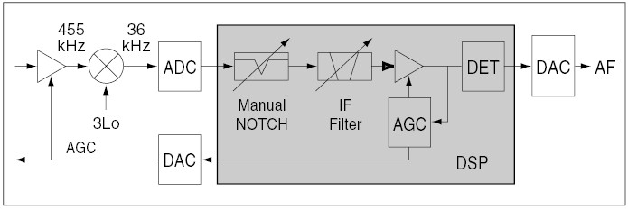
To prevent swamping (desensing by strong unwanted signals in the presence of the weak desired signal), the AGC derivation point must follow IF selectivity filtering. This is accomplished in the digital domain by placing the AGC process downstream of the manual notch and IF filter processes, as shown in Fig.1.
The AGC signal is derived within the DSP, after the IF selectivity process but prior to the demodulation process. This signal varies the gain ahead of the demodulation process (in the digital domain). The associated bitstream also feeds a dedicatedDAC which drives the analogue AGC line controlling the gain of the receiver's 1st IF amplifier. The main DAC and the AGC DAC are driven by a common serial data output from the DSP IC on which the baseband and AGC bitstreams are multiplexed.
The upshot of all this is that signals outside the DSP IF passband do not develop AGC voltage. Ref. 4 offers additional notes on AGC in the IC-756Pro series. This single-loop topology is also used in the IC-7000, IC-7400 and IC-746Pro.
To meet the potentially conflicting requirements of high S/Q ratio at low RF input levels, and avoidance of ADC over-ranging under strong-signal conditions, the DSP AGC process must provide the entire AGC gain-control range (Note 1), and the ADC must have sufficient dynamic range to handle the desired and interfering signals without distortion (Note 2).
For these reasons, Icom selected a 24-bit ADC with at least 110 dBdynamic range (approximately 120 dB when the headroom required to avoid over-ranging the ADC and DAC on signal peaks is taken into consideration.)
There are 4 AGC menu settings: FAST, MID, SLOW and OFF (Note 3). The values for the first three settings are individually configurable. These settings vary the time constant (hang/decay time.)
Note 1: To control the AGC attack response properly and to ensure an optimum input level to the DAC, it is necessary to adjust the IF gain in the digital domain even after the IF filter process. If the gain adjustment range within the DSP is set at 60 dB, it is necessary to obtain a wider dynamic range, as the noise floor israised by 60 dB under full-gain (weak-signal) conditions where AGC is not applied.
Note 2: If the signal is distorted before entering the ADC, distortioncomponents can degrade the desired signal. Such degradation is extremely difficult to remove by post-processing.
Note 3: To avoid over-ranging the ADC, the AGC should not be turned off under normal operating conditions.
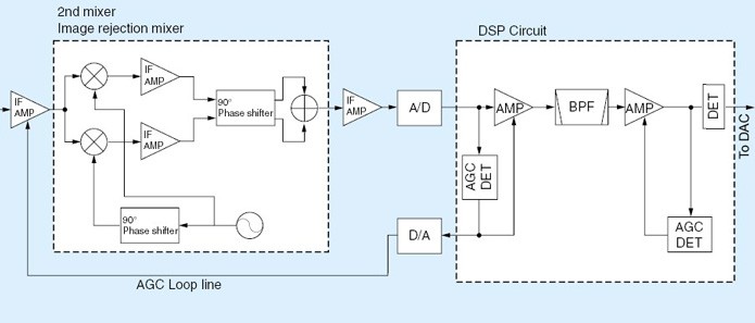 |
The IC-7700 and IC-7800 have two AGC loops, which we will term primary and secondary. (See Fig.2.) The primary AGC loop derives its AGC voltage within the DSP unit, at the input of the gain-controlled amplifier preceding the BPF (IF filter process). It adjusts the input level to the BPF, and also feeds a dedicated DAC which drives the analogue AGC line controlling the gain of the receiver's 1st IF amplifier following the 1st IF roofing filter. This AGC loop prevents strong signals outside the BPF passband from saturating the 1st IF amplifier and 2nd mixer, and improves the dynamic range in regard to adjacent signals.Here is a concise description of the IC-7800's AGC subsystem.
The secondary AGC loop derives its AGC voltage at the digital IF filter (BPF) output which has only passed the desired signal, thus exploiting the digital IF filter to the full. As the primary AGC loop will already have adjusted the gain distribution in the analogue RF/IF chain preceding the ADC, there is a high degree of confidence that only the desired signal will enter the secondary AGC loop. This loop will maintain the digital signal level at the DAC input within the optimum range for decoding.
In addition to the menu-configurable AGC time constants (slow, medium and fast), the manual AGC control offers fine adjustment of AGC hang/decay time.
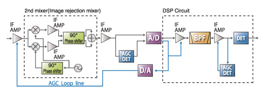 |
The IC-7600 also has primary and secondary AGC loops. (See Fig.3.) In contrast to the IC-7700 and IC-7800, the primary AGC detector is analogue. Its output is digitised in the ADC and then processed within the DSP. In the DSP circuit, the primary AGC adjusts the gain of the IF amplifier preceding the BPF (IF filter process). It also feeds a dedicated DAC which drives the analogue AGC line controlling the gain of the receiver's 1st IF amplifier following the 1st IF roofing filter. This AGC loop prevents strong signals outside the BPF passband from saturating the 1st IF amplifier and 2nd mixer, and improves the dynamic range in regard to adjacent signals.
As in the IC-7700 and IC-7800, the secondary AGC loop derives its AGC voltage at the digital IF filter (BPF) output which has only passed the desired signal, thus exploiting the digital IF filter to the full. As the primary AGC loop will already have adjusted the gain distribution in the analogue RF/IF chain preceding the ADC, there is a high degree of confidence that only the desired signal will enter the secondary AGC loop. This loop will maintain the digital signal level at the DAC input within the optimum range for decoding.
This architecture prevents strong adjacent signals from "pumping" the AGC and allows maximum dynamic range in the ADC and DSP.
Attack time: The AGC attack time in a DSP-based radio is a trade-off. If it is too long, there is a risk that a fast-rising signal wave-front will instantaneously over-range the ADC. If the AGC loop is DSP-derived, there will then be no AGC action until the spike disappears. If the signal is of constant level, the entire receiver will remain locked up until the signal is removed, as there is now no AGC action as long as the ADC is driven to or beyond 0 dBFS.Contrastingly, if the AGC attack time is too short, the AGC will respond to a fast-rising signal wave-front or spike. This can lead to clamping if the decay time is too long.
For this reason, the attack time is optimised as a function of the overall RF/IF/DSP system, and is not normally user-adjustable.
Adaptive AGC: Impulse loading (baseband "ticks" and AGC clamping caused by very short noise impulses) can be prevented if the AGC algorithm is sufficiently "smart" to perform a simple real-time signature analysis of the noise spike, and change the AGC profile dynamically (longer attack, shorter decay) if it recognises an impulse (as opposed to the leading flank of a signal waveform.) Any "on-the-fly" modification of the AGC parameters derived from signal fingerprinting must take place in quasi-real-time; the DSP must have sufficient "horsepower" to achieve this. I suspect that the IC-7700 and IC-7800 may well incorporate such a feature. (Reference 1)
AGC/NB interaction: In a receiver in which the noise blanker (NB) and AGC are both DSP processes (IC-7000, IC-7200, IC-7600, IC-7700, IC-7800, IC-R9500) the NB can be used to advantage in certain cases to blank extremely fast-rising noise spikes which might otherwise provoke AGC action and clamping. A DSP NB implementation renders all the more important the requirement to protect the ADC from over-ranging.
The noise blanker, which is ahead of the AGC in the DSP task list, can be viewed as an extension of the AGC. The NB should be carefully adjusted to suppress spikes without causing distortion due to gating on the voice peaks of strong signals lying outside the IF passband.
Interaction between primary and secondary loops: I suspect that in the IC-7700 and IC-7800, the AGC signals derived in the primary and secondary loops are compared in the DSP AGC process. It makes sense that if the primary loop detects a signal which has passed through the roofing filter, but the secondary loop does not "see" that signal in the DSP-IF filter passband, the primary loop will be inhibited from reducing the gain of the 1st IF amplifier. The purpose of this is to prevent strong undesired signals within the roofing-filter window, but falling outside the DSP IF filter passband, from swamping the receiver.
| Loop interaction test procedure: One can test for this condition as follows. Select a 500 Hz CW filter and the 3 or 6 kHz roofing filter, inject a signal at about -90 dBm from a signal generator into the antenna socket, note the S-meter reading and then tune the signal slowly across the DSP-IF passband. The S-meter reading should fall to zero, and the recovered audio tone should disappear. Now increase the generator output until the signal deflects the S-meter again. Ideally, the S-meter should not move until the test signal level reaches a point (typically -30 dBm or higher) where reciprocal mixing noise is at a sufficiently high level to develop AGC voltage. |
AGC performance specifications: In the commercial and mil/gov HF sphere, designers test for AGC control range, attack transient response, hang time and decay time. The only ITU-R requirement I could find was in Recommendation SM.1055, where impairment to AGC must be prevented if the interference burst time is greater than the AGC attack time in a "conventional digital receiver" or greater than 1 mS in an AM voice receiver.
I believe that no AGC system should ever respond to a transient shorter than 50 nS. But as outlinedabove, the optimum AGC attack time is a trade-off between "too long", leading to instantaneous ADC over-ranging on noise impulses, and "too short" causing AGC clamping on RF spikes. The attack time should also be short enough to respond correctly to the leading edge of a CW or digital-mode signal.
The attack time concerns only the leading edge of a signal envelope or noise event. The hang time should in all cases be longer than the symbol rate (CW), syllabic rate (voice) or the typical interval between noise impulses. Static is a "bear" to deal with, as it has no predictable pattern.
Sabin et al., "HF Radio Systems & Circuits", ch. 4, pp.145-148, AGC Design. (Read References 1 & 2)
Sabin et al., "HF Radio Systems & Circuits", Section 8.6 (Digital AGC Methods), p. 341. This section covers the topic very thoroughly.
IC-756Pro II Technical Report, Section 4, p. 10: AGC.
Further discussion on AGC and front-end AGC.
Copyright © 2007-2009, A. Farson VA7OJ/AB4OJ. Images courtesy Icom Inc.
Last updated: 09/25/2019
![]()